

Haz
-
Posts
25 -
Joined
-
Last visited
-
Days Won
8


Haz's Achievements
")
Newbie (1/14)
-
 enigma-2 reacted to a post in a topic:
Steering wheel
enigma-2 reacted to a post in a topic:
Steering wheel
-
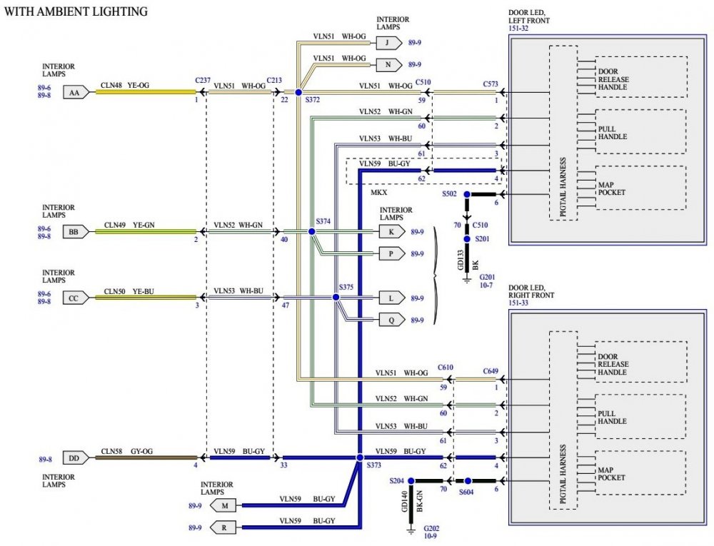
From the 2015 MKX Workshop Manual... Ambient Lighting The ambient lighting subsystem provides illumination to the center console cupholders, the storage bin, the door map pockets, the door pull handles, the door release handles, and the front and rear footwells for illuminated entry or when the ignition is in run with the parking lamps on. The ambient lighting is controlled using the touch screen display in the center of the instrument panel. When the illuminated entry feature is active, the ambient lighting defaults to a pre-set color and brightness setting. When all the doors are closed and the illuminated entry is no longer active, the ambient lighting returns to the last color and brightness setting that was set by the operator. The touch screen display is used to select one of 7 color combinations or turn the ambient lighting feature on or off. The ambient lighting system retains the last color setting and brightness between uses. For vehicles with memory seats, the ambient lighting color can also be set to correspond to the Driver 1 or Driver 2 settings. and... Ambient Lighting The HVAC module controls the ambient lighting system. When requested, the HVAC module provides voltage and ground to the LEDs. There are 3 LEDs (Edge) (red, blue and green) or 4 LEDs (MKX) (red, blue, green and white) housed within each LED assembly. By illuminating various color combinations, the LEDs are able to produce 7 different colors of ambient light. The HVAC module receives input from the Accessory Protocol Interface Module (APIM) and the Body Control Module (BCM) over the communication network for color and brightness settings. The display interface in the center of the instrument panel is used to cycle through different color variations or turn the ambient lighting feature on or off. The APIM communicates messages over the High Speed Controller Area Network (HS-CAN) to the Body Control Module (BCM) . The BCM gateways the messages to the HVAC module over the Medium Speed Controller Area Network (MS-CAN) . The HVAC module retains the last color and brightness setting between uses. and... Door Panel Ambient Lighting Wiring Diagram We've always run "white" as our Ambient selection, so I had to do a test to assess the other colors' behavior. All colors shown in the MFT color-carousel do display correctly in all Ambient locations on our MKX, including the door map pockets. When an Ambient color other than "white" is selected and the a door is opened, all locations' displayed Ambient color changes to "white", consistent with the Workshop Manual description. I need to do a more digging through wiring diagrams before I can offer additional comment. Good luck!
-
Having likely rotated your Nautilus' tires two-or-three times at 18,000 miles, has the excessive inner/outer wear pattern been established on all four tires? Good luck!
-
Automatic wipers wipe with no moisture
Haz replied to lesmower's topic in Glass, Lenses, Lighting, Mirrors & Wipers
This instructional Ford video on Rain Sensing Wipers operation is worth more than my thousand words. Good luck! -
Automatic wipers wipe with no moisture
Haz replied to lesmower's topic in Glass, Lenses, Lighting, Mirrors & Wipers
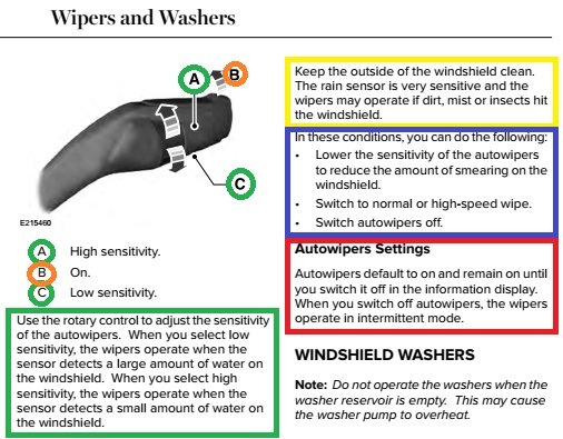
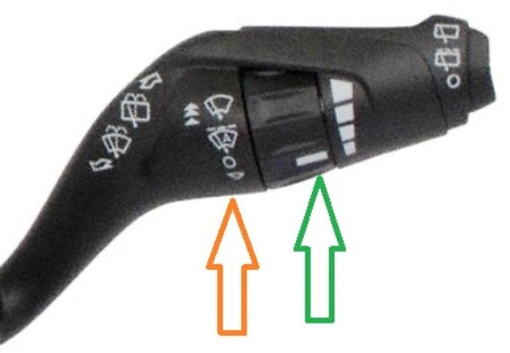
The crux of your question seems to be 'Something has changed' and 'What can I do about it'. In this case, the existing rain sensor was removed from the faulty windshield and remounted to the replacement windshield, with more-than-previous spurious wipes occurring after the repair was completed. Let's start with the technical, and then we'll address the practical. Rain sensor photo from FordParts.com... From the 2018 MKX Workshop Manual... Rain Sensor The rain sensor uses an infrared beam to optically sense water on the windshield. The intensity of the reflected beam is measured and compared to the intensity of the transmitted beam. If there is water on the surface of the windshield the beam distorts, reducing the intensity of the beam. If the beam is not reflected completely, it is interpreted as rain on the windshield and the windshield wipers are activated. A gel-type lens is used as the interface between the rain sensor and the windshield. If the lens is missing or damaged, the rain sensing wipers can be inoperative. The rain sensor gel-type lens cannot be replaced separately on a rain sensor of this type. Rain Sensitive Wipers (if equipped) When equipped, the rain sensitive wiper feature replaces the intermittent wiper feature. The rain sensitive feature is active when the wiper/washer switch is in any of the 6 auto/intermittent sensitivity settings. The setting closest to OFF is the least sensitive to moisture, the highest setting being the most sensitive to moisture. The rain sensor sends data through the LIN to the windshield wiper motor. Based on the data received from the rain sensor and the auto/intermittent setting from the wiper/washer switch, the system automatically activates and adjusts the wiper speed and frequency when moisture is detected on the windshield. If a fault is detected with the rain sensitive feature, the windshield wipers change to a default intermittent mode. The timing of the wipers correspond to a standard intermittent setting based on the auto/intermittent sensitivity setting on the wiper/washer switch. Intermittent Wipers When the wiper/washer switch is in an intermittent setting, the windshield wiper motor activates at timed intervals. The lower the setting, the longer the interval between wipes. Wiper/Washer Switch The wiper/washer switch is mounted directly to the SCCM . The windshield wiper/washer inputs to the SCCM are: Mist wipe Windshield wash Off AUTO 1/INT 1 AUTO 2/INT 2 AUTO 3/INT 3 AUTO 4/INT 4 AUTO 5/INT 5 AUTO 6/INT 6 Low High Workshop Manual diagnostic Pinpoint Test "F", edited to focus upon Rain Sensor function... F7 CHECK THE WINDSHIELD GLASS FOR STREAKING Ignition ON. Turn the wiper/washer switch to the low speed wiper setting and while applying water to the windshield surface. Observe the wipe quality, especially around the area of the rain sensor. Is any streaking present on the windshield around the area of the rain sensor? Yes GO to F8 No GO to F10 F8 CHECK THE WINDSHIELD WIPER BLADES FOR STREAKING Ignition OFF. Clean the windshield glass with glass cleaner. Clean the wiper blades with isopropyl alcohol swabs. Wipe the entire length of the wiper blades. Ignition ON. Place the wiper/washer switch to the low speed wiper setting and while applying water to the windshield surface. Observe the wipe quality, especially around the area of the rain sensor. Was there noticeable improvement in the wipe quality after cleaning the glass and the wiper blades? Yes GO to F9 No INSTALL new wiper blades. GO to F9 F9 RECHECK THE RAIN SENSITIVE WIPERS OPERATION Place the wiper/washer switch to the auto/intermittent 5 setting (most sensitive to moisture) while applying water on the windshield above the rain sensor. Do the wipers operate when water is applied to the windshield surface? Yes The system is operating correctly at this time. The concern may have been caused by poor wipe quality on the windshield around the rain sensor. No GO to F10 F10 CHECK FOR THE PRESENCE OF THE LENS GEL Ignition OFF. Lightly press the rain sensor against the windshield and release the rain sensor clips. Does the rain sensor remain adhered to the windshield? Yes ATTACH the retaining clips. GO to F11 No The sensor gel-type lens is missing or damaged. INSTALL a new rain sensor. REFER to: Rain Sensor (501-16 Wipers and Washers, Removal and Installation). PDF download link to document > Rain Sensor - Removal and Installation - 2018 MKX Workshop Manual.pdf F11 INSPECT THE RAIN SENSOR MOUNTING AREA NOTE: The rain sensor gel-type lens can be damaged or contaminated during rain sensor removal, rain sensor bracket separation or incorrect installation. From the outside of the vehicle, inspect the area of the windshield glass where the rain sensor is mounted. The rain sensor contact area should appear black, with no bubbles, air pockets or contaminants between the windshield glass and the rain sensor. Does the rain sensor contact area appear black, with no bubbles, air pockets or contaminants between the windshield glass and the rain sensor? Yes GO to F12 No REMOVE and INSTALL the rain sensor correctly. REFER to: Rain Sensor (501-16 Wipers and Washers, Removal and Installation) > PDF download link in Step F10 section, above. TEST the system for normal operation. And now, on to the practical: Color augmented 2018 MKX Owners Manual section and Wiper-Washer Multi-Function Switch photo from FordParts.com... Observations from immediately above... Yellow box - A dirty/dusty windshield in vicinity of rain sensor can cause spurious wipes; Green box - Setting sensitivity to low, in photo, green arrow, diminishes risk of spurious wipes; Orange circles and in photo, orange arrow - moving right stalk upward or downward, sets high speed wipe, low speed wipe, autowipe (rain or intermittent), off/no wipe, mist wipe. After performing Pinpoint Test "F" conditional evaluations, if spurious wipes are still a problem, just set the stalk in "Off" position to eliminate spurious wipes. The following are PDF download links to relevant Workshop Manual sections... Wipers and Washers - System Operation and Component Description - 2018 MKX Workshop Manual.pdf Rain Sensor - Removal and Installation - 2018 MKX Workshop Manual.pdf Interior Rear View Mirror - Removal and Installation - 2018 MKX Workshop Manual.pdf Good luck!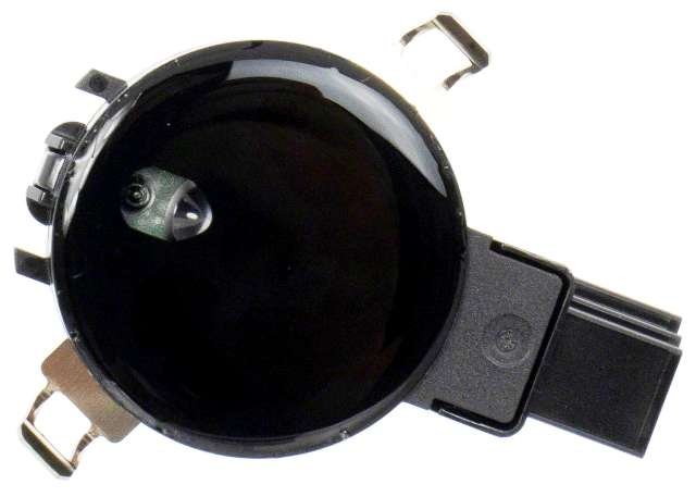
-
Oil pressure sensor location 2016 mkx 2.7
Haz replied to 19green97's topic in Maintenance, Recalls & TSBs
If your further investigation points to the oil pan as a leak source, the below Technical Service Bulletin relating to that condition on 2.7L/3.0L EcoBoost engines may be helpful... TSB 19-2332 - 2.7L & 3.0L EcoBoost - Oil Pan Leaking - Issued 11-04-2019.pdf Good luck! -
Oil pressure sensor location 2016 mkx 2.7
Haz replied to 19green97's topic in Maintenance, Recalls & TSBs
Beginning with the engine oil pressure sensor, below are PDF download links to relevant sections of the 2016 MKX Workshop Manual... Engine Oil Pressure (EOP) Sensor - Location Illustration - 2016 MKX Workshop Manual .pdf Engine Oil Pressure (EOP) Sensor - Removal and Installation - 2016 MKX Workshop Manual.pdf Engine Oil Pressure (EOP) Sensor - Connector C1642 Wiring Details - 2016 MKX Workshop Manual .pdf Engine Oil Pressure (EOP) Sensor - Wiring Diagram - 2016 MKX Workshop Manual .pdf Your photos show relatively widespread surfaces that have been dampened & soiled while driving at speed. The Workshop Manual provides the following methods that a dealership technician would use to evaluate potential points of leakage... Engine Oil Leaks NOTE: If an overnight drive is done, the fan air or road air blast can cause erroneous readings. NOTE: When diagnosing engine oil leaks, the source and location of the leak must be positively identified prior to repair. Prior to carrying out this procedure, clean the cylinder block, cylinder heads, valve covers, oil pan and flywheel/flexplate with a suitable solvent to remove all traces of oil. Engine Oil Leaks - Fluorescent Oil Additive Method Use the 12 Volt Master UV Diagnostic Inspection Kit to carry out the following procedure for oil leak diagnosis. Add 29.6 ml (1 oz) of Dye-Lite® Gasoline Engine Oil Leak Detection Dye to a minimum of 0.47L (1/2 qt) and a maximum of 0.95L (1 qt) engine oil and fill through the engine oil fill. Thoroughly premix the gasoline engine oil leak detection dye or it will not have enough time to reach the crankcase, oil galleries and seal surfaces during this particular 15 minute test. The additive must be mixed well with oil and added through the oil fill. Check the level on the oil level indicator to determine what amount of oil to premix. If it is in the middle of the crosshatch area or below the full mark, use 0.95L (1 qt). If it is at the full mark, use 0.47L (1/2 qt). Run the engine for 15 minutes. Stop the engine and inspect all seal and gasket areas for leaks using the UV Leak Detector Kit. A clear bright yellow or orange area will identify the leak. For extremely small leaks, several hours may be required for the leak to appear. At the end of test, make sure the oil level is within the upper and lower oil indicator marks. Remove oil as necessary if it registers above the full mark. Leakage Points - Underhood Examine the following areas for oil leakage: Valve cover gaskets Cylinder head gaskets Oil cooler, if equipped Oil filter adapter Engine front cover Oil filter adapter and filter body Oil level indicator tube connection Oil pressure switch or EOP sensor Turbocharger oil tubes Leakage Points - Under Engine, With Vehicle on Hoist Examine the following areas for oil leakage: Oil pan gaskets Oil pan sealer Engine front cover gasket Crankshaft front seal Crankshaft rear oil seal Oil filter adapter and filter body Oil cooler, if equipped Turbocharger oil tubes Leakage Points - With Transmission and Flywheel/Flexplate Removed Examine the following areas for oil leakage: Crankshaft rear oil seal Rear main bearing cap parting line Flexplate mounting bolt holes (with flexplate installed) Pipe plugs at the end of oil passages Whether you choose to do it yourself without the benefit of fluorescent oil additive, or, if you prefer to hand off the task to dealership Service personnel, a thorough cleaning of the engine is the first step toward clearly recognizing the source of the leak. Good luck!Sensor-LocationIllustration-2016MKXWorkshopManual.jpg.7dbb9d9d150aa421752a5dbae82f0225.jpg)
-
Oil pressure sensor location 2016 mkx 2.7
Haz replied to 19green97's topic in Maintenance, Recalls & TSBs
Because the R&I procedure does not list draining the oil as a process-step, I doubt that it should be necessary, but it would be prudent to have a container at hand to catch drips that may occur initially when you remove the sensor/solenoid. And it is odd that parts department naming often does not match Workshop Manual descriptions. Good luck! -
 19green97 reacted to a post in a topic:
Oil pressure sensor location 2016 mkx 2.7
19green97 reacted to a post in a topic:
Oil pressure sensor location 2016 mkx 2.7
-
Customer Satisfaction Program 21B09 has been extended to March 31, 2023. Document download links below... Customer Satisfaction Program 21B09 Supplement 1 - 3G to 4G Upgrade - 2016-17 MKX - Dealer Letter.pdf Customer Satisfaction Program 21B09 Supplement 1 - 3G to 4G Upgrade - 2016-17 MKX Service Procedure.pdf Lincoln Owner App Instructions - 4G setup after Customer Satisfaction Program 21B09 Completed.pdf Customer Satisfaction Program 21B09 Supplement 1 - 3G to 4G Upgrade - 2016-17 MKX Owner Letter.pdf Good luck!
-
2023 Order Guide and Timetable
Haz replied to akirby's topic in Buying, Ordering and Leasing a Lincoln MKX / Nautilus
2023 Nautilus Order Guide.pdf (Download link) Good luck! -
Oil pressure sensor location 2016 mkx 2.7
Haz replied to 19green97's topic in Maintenance, Recalls & TSBs
Perhaps you are referring to the Oil Pressure Control Solenoid, the red-circled Item #1, shown in the below illustrations?... If so, this Service Procedure should be helpful to you: Oil Pressure Control Solenoid - Removal and Installation - 2016 MKX Workshop Manual.pdf (Download Link) Good luck!

-
https://www.car-part.com/noninterchange.htm
-
 Michael reacted to a post in a topic:
2012 8mm intake bolt snapped Lincoln MKX
Michael reacted to a post in a topic:
2012 8mm intake bolt snapped Lincoln MKX
-
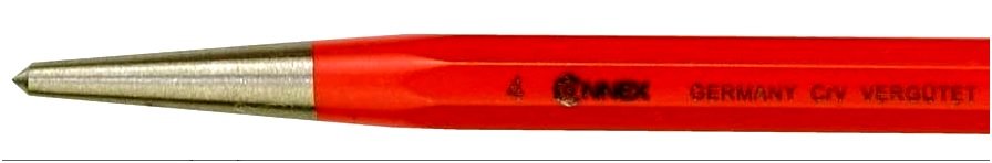
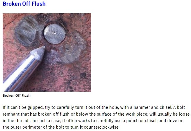
The bolt breaking as you tightened it makes it likely that the broken portion remaining in the threaded brass insert is not seized or stuck, but may be rotated in a counter-clockwise direction by using a small hardened center-punch and hammer, according to the below-pictured instructions. If you don't have a center punch in your tool box, it should be an easy find at your local hardware store in the hand tool aisle. Below are PDF links to relevant 2012 Edge-MKX Workshop Manual sections on in-vehicle Upper and Lower Intake Manifold repairs, which include manifold bolt part numbers. You may wish to try to obtain replacement manifold bolt(s) from your local Ford or Lincoln dealership parts department and/or at a local auto parts store, due to the high-heat environment of the engine compartment. Hopefully, you will not have to resort to drilling the broken portion out to use an extractor tool, which you should also be able to buy at your local hardware and/or auto parts store. Good luck! Upper Intake Manifold In-Vehicle Repair - 3.7L - 2012 Edge-MKX Workshop Manual.pdf Lower Intake Manifold In-Vehicle Repair - 3.7L - 2012 Edge-MKX Workshop Manual.pdf
-
Below are PDF download links to the 2012 Edge-MKX Workshop Manual information you requested... Good luck! 3.7L Ignition Specifications - 2012 Edge-MKX Workshop Manual.pdf 3.7L Spark Plug Gap & Torque Specs - 2012 Edge-MKX Workshop Manual.pdf
-
CARR142 reacted to a post in a topic:
2012 Lincoln MKX
-
Haz reacted to a post in a topic:
2012 Lincoln MKX
-
Below are PDF download links to relevant sections of the 2012 Edge-MKX Workshop Manual... Good luck! Throttle Body — Exploded View - 2012 Edge-MKX Workshop Manual.pdf Intake Air System Components — Exploded View - 2012 Edge-MKX Workshop Manual.pdf Upper Intake Manifold — Removal - 2012 Edge-MKX Workshop Manual.pdf Engine Appearance Cover — Exploded View - 2012 Edge-MKX Workshop Manual.pdf MACT Ford Edge video guidance - 51 minute spark plug change 2011 Ford Edge
-
Tiffany reacted to a post in a topic:
Hope it's not a lemon ...
-
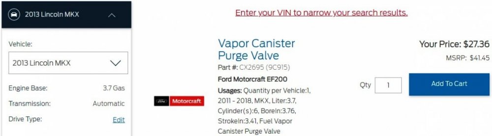
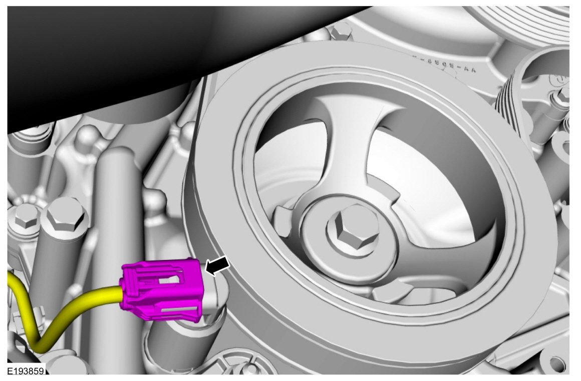
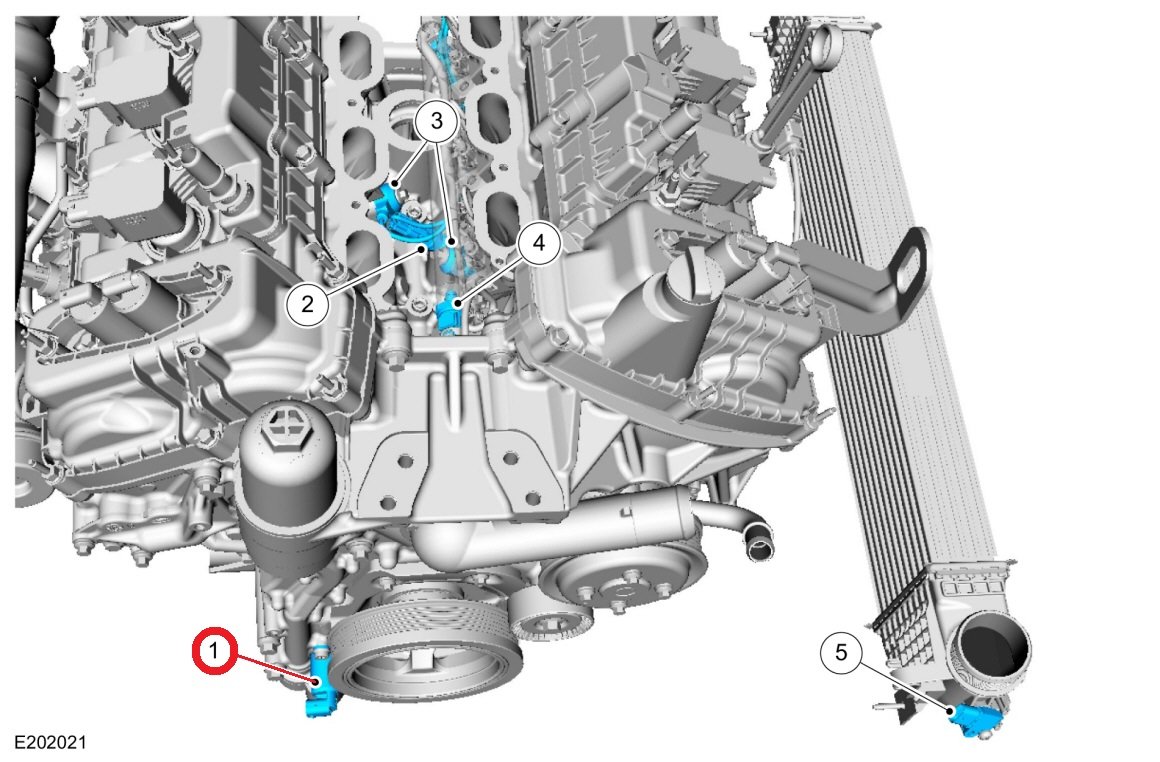
...which is not as costly as an Oxygen Sensor... (from Parts.Ford.com) If you are a do-it-yourself owner, these YouTube videos describe the fairly easy replacement procedure... And this one offers a bit more technical detail on the Purge Valve itself... Good luck!